As a key component to achieve the performance of aero-engines, blades have typical characteristics such as thin-walled, special-shaped, complex structures, difficult materials to process, and high requirements for processing accuracy and surface quality. How to achieve precise and efficient processing of blades is a major challenge in the current aero-engine manufacturing field. Through the analysis of the key factors affecting blade processing accuracy, the current status of research on blade precision processing technology and equipment is comprehensively summarized, and the development trend of aero-engine blade processing technology is prospected.
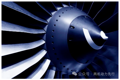
In the aerospace industry, lightweight, high-strength thin-walled parts are widely used and are key components for achieving the performance of important equipment such as aircraft engines [1]. For example, the titanium alloy fan blades of large bypass ratio aircraft engines (see Figure 1) can be up to 1 meter long, with complex blade profiles and damping platform structures, and the thickness of the thinnest part is only 1.2 mm, which is a typical large-size thin-walled special-shaped part [2]. As a typical thin-walled special-shaped weak rigidity part, the blade is prone to processing deformation and vibration during the processing [3]. These problems seriously affect the processing accuracy and surface quality of the blade.
The performance of the engine depends largely on the manufacturing level of the blades. During the operation of the engine, the blades need to work stably under extreme operating environments such as high temperature and high pressure. This requires that the blade material must have good strength, fatigue resistance, and high temperature corrosion resistance, and ensure structural stability [2]. Usually, titanium alloys or high temperature alloys are used for aircraft engine blades. However, titanium alloys and high temperature alloys have poor machinability. During the cutting process, the cutting force is large and the tool wears quickly. As the tool wear increases, the cutting force will further increase, resulting in more serious machining deformation and vibration, resulting in low dimensional accuracy and poor surface quality of parts. In order to meet the service performance requirements of the engine under extreme working conditions, the machining accuracy and surface quality of the blades are extremely high. Taking the titanium alloy fan blades used in a domestically produced high bypass ratio turbofan engine as an example, the total length of the blade is 681mm, while the thickness is less than 6mm. The profile requirement is -0.12 to +0.03mm, the dimensional accuracy of the inlet and exhaust edges is -0.05 to +0.06mm, the torsion error of the blade section is within ±10′, and the surface roughness value Ra is better than 0.4μm. This usually requires precision machining on a five-axis CNC machine tool. However, due to the blade's weak rigidity, complex structure and difficult-to-process materials, in order to ensure machining accuracy and quality, process personnel have to adjust the cutting parameters multiple times during the machining process, which seriously limits the performance of the CNC machining center and causes huge efficiency waste [4]. Therefore, with the rapid development of CNC machining technology, how to achieve deformation control and vibration suppression for thin-walled parts machining and give full play to the machining capabilities of CNC machining centers has become an urgent need for advanced manufacturing companies.
The research on deformation control technology of thin-walled weak rigid parts has attracted the attention of engineers and researchers for a long time. In early production practice, people often use the waterline strategy of alternating milling on both sides of thin-walled structures, which can easily reduce the adverse effects of deformation and vibration on dimensional accuracy to a certain extent. In addition, there is also a way to improve processing rigidity by setting prefabricated sacrificial structures such as reinforcing ribs.
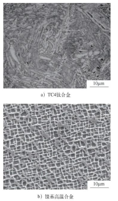
In order to meet the requirements of stable service under high temperature and high pressure environment, the commonly used materials for aircraft engine blades are titanium alloys or high-temperature alloys. In recent years, titanium-aluminum intermetallic compounds have also become a blade material with great application potential. Titanium alloys have the characteristics of low thermal conductivity, low plasticity, low elastic modulus and strong affinity, which makes them have problems such as large cutting force, high cutting temperature, severe work hardening and large tool wear during cutting. They are typical difficult-to-cut materials (microstructure morphology see Figure 2a) [7]. The main characteristics of high-temperature alloys are high plasticity and strength, poor thermal conductivity, and a large amount of dense solid solution inside [8]. Plastic deformation during cutting causes severe distortion of the lattice, high deformation resistance, large cutting force and severe cold hardening phenomenon, which are also typical difficult-to-cut materials (microstructure morphology see Figure 2b). Therefore, it is very important to develop efficient and precise cutting technology for difficult-to-cut materials such as titanium alloys and high-temperature alloys. In order to achieve efficient and precise machining of difficult-to-cut materials, domestic and foreign scholars have conducted in-depth research from the perspectives of innovative cutting methods, optimal machining tool materials and optimized cutting parameters.
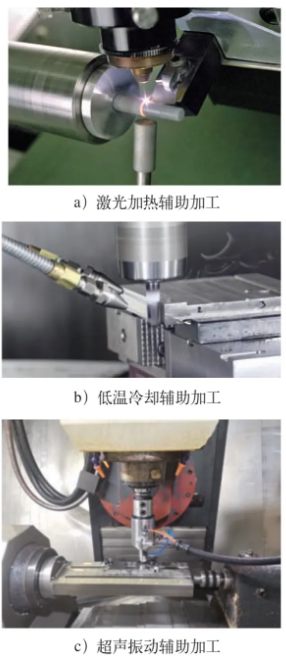
In terms of innovative research and development of cutting methods, scholars have introduced auxiliary means such as laser heating and cryogenic cooling to improve the machinability of materials and achieve efficient cutting. The working principle of laser heating assisted processing [9] (see Figure 3a) is to focus a high-power laser beam on the workpiece surface in front of the cutting edge, soften the material by local heating of the beam, reduce the yield strength of the material, thereby reducing the cutting force and tool wear, and improving the quality and efficiency of cutting. Cryogenic cooling assisted processing [10] (see Figure 3b) uses liquid nitrogen, high-pressure carbon dioxide gas and other cooling media to spray on the cutting part to cool the cutting process, avoid the problem of excessive local cutting temperature caused by poor thermal conductivity of the material, and make the workpiece locally cold and brittle, thereby enhancing the chip breaking effect. The Nuclear AMRC company in the UK successfully used high-pressure carbon dioxide gas to cool the titanium alloy processing process. Compared with the dry cutting state, the analysis shows that cryogenic cooling assisted processing can not only reduce the cutting force and improve the quality of the cutting surface, but also effectively reduce tool wear and increase the service life of the tool. In addition, ultrasonic vibration assisted processing [11, 12] (see Figure 3c) is also an effective method for efficient cutting of difficult-to-process materials. By applying high-frequency, small-amplitude vibrations to the tool, intermittent separation between the tool and the workpiece is achieved during the machining process, which changes the material removal mechanism, enhances the stability of dynamic cutting, effectively avoids friction between the tool and the machined surface, reduces cutting temperature and cutting force, reduces surface roughness values, and reduces tool wear. Its excellent process effects have received widespread attention.
For difficult-to-cut materials such as titanium alloys, optimizing tool materials can effectively improve cutting results [8, 13]. Studies have shown that for titanium alloy processing, different tools can be selected according to the processing speed. For low-speed cutting, high-cobalt high-speed steel is used, for medium-speed cutting, cemented carbide tools with aluminum oxide coating are used, and for high-speed cutting, cubic boron nitride (CBN) tools are used; for high-temperature alloy processing, high-vanadium high-speed steel or YG cemented carbide tools with high hardness and good wear resistance should be used for processing.
Cutting parameters are also an important factor affecting the machining effect. Using appropriate cutting parameters for the corresponding materials can effectively improve the machining quality and efficiency. Taking the cutting speed parameter as an example, low cutting speed can easily form a built-up edge area on the material surface, reducing the surface machining accuracy; high cutting speed can easily cause heat accumulation, causing burns to the workpiece and tool. In this regard, Professor Zhai Yuansheng's team at Harbin University of Science and Technology analyzed the mechanical and physical properties of commonly used difficult-to-machine materials and summarized a recommended table of cutting speeds for difficult-to-machine materials through orthogonal machining experiments [14] (see Table 1). Using the tools and cutting speeds recommended in the table for machining can effectively reduce machining defects and tool wear, and improve machining quality.
In recent years, with the rapid development of the aviation industry and the rising market demand, the requirements for efficient and precise processing of thin-walled blades have been increasingly increased, and the demand for higher-precision deformation control technology has become more urgent. In the context of intelligent manufacturing technology, combining modern electronic information technology to achieve intelligent control of deformation and vibration of aircraft engine blade processing has become a hot topic for many researchers. Introducing intelligent CNC systems into the precision processing of complex curved surfaces of blades, and actively compensating for errors in the processing process based on intelligent CNC systems, can effectively suppress deformation and vibration.
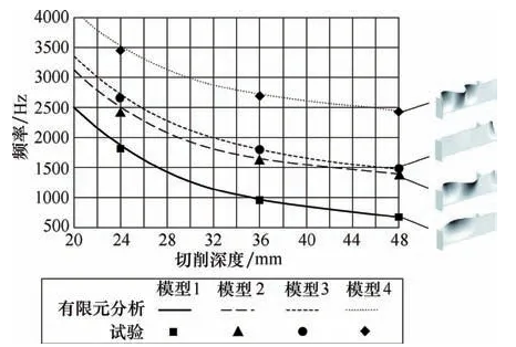
For active error compensation in the machining process, in order to achieve the optimization and control of machining parameters such as tool path, it is necessary to first obtain the influence of process parameters on machining deformation and vibration. There are two commonly used methods: one is to analyze and reason the results of each tool pass through on-machine measurement and error analysis [15]; the other is to establish a prediction model for machining deformation and vibration through methods such as dynamic analysis [16], finite element modeling [17], experiments [18] and neural networks [19] (see Figure 4).
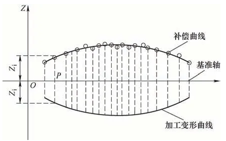
Based on the above prediction model or on-machine measurement technology, people can optimize and even control the machining parameters in real time. The mainstream direction is to compensate for the errors caused by deformation and vibration by replanning the tool path. The commonly used method in this direction is the "mirror compensation method" [20] (see Figure 5). This method compensates the deformation of a single cutting by correcting the nominal tool trajectory. However, a single compensation will produce new machining deformation. Therefore, it is necessary to establish an iterative relationship between the cutting force and the machining deformation through multiple compensations to correct the deformation one by one. In addition to the method of active error compensation based on tool path planning, many scholars are also studying how to control deformation and vibration by optimizing and controlling cutting parameters and tool parameters. For the cutting of a certain type of aircraft engine blade, the machining parameters were changed for multiple rounds of orthogonal tests. Based on the test data, the influence of each cutting parameter and tool parameter on the blade machining deformation and vibration response was analyzed [21-23]. An empirical prediction model was established to optimize the machining parameters, effectively reduce machining deformation, and suppress cutting vibration.
Based on the above models and methods, many companies have developed or improved the CNC systems of CNC machining centers to achieve real-time adaptive control of thin-walled parts processing parameters. The optimal milling system of Israel's OMAT company [24] is a typical representative in this field. It mainly adjusts the feed speed through adaptive technology to achieve the purpose of constant force milling and realize high-efficiency and high-quality processing of complex products. In addition, Beijing Jingdiao also applied similar technology in the classic technical case of completing eggshell surface pattern engraving through on-machine measurement adaptive compensation [25]. THERRIEN of GE in the United States [26] proposed a real-time correction method for CNC machining codes during machining, which provided a basic technical means for adaptive machining and real-time control of complex thin-walled blades. The European Union's automated repair system for aircraft engine turbine components (AROSATEC) realizes adaptive precision milling after the blade is repaired by additive manufacturing, and has been applied to the blade repair production of Germany's MTU company and Ireland's SIFCO company [27].
Using intelligent process equipment to improve the rigidity of the process system and improve the damping characteristics is also an effective way to suppress the deformation and vibration of thin-walled blade processing, improve processing accuracy, and improve surface quality. In recent years, a large number of different process equipment have been used in the processing of various types of aero-engine blades [28]. Since aero-engine blades generally have thin-walled and irregular structural characteristics, a small clamping and positioning area, low processing rigidity, and local deformation under the action of cutting loads, blade processing equipment usually applies auxiliary support to the workpiece on the basis of satisfying the six-point positioning principle [29] to optimize the rigidity of the process system and suppress processing deformation. Thin-walled and irregular curved surfaces put forward two requirements for the positioning and clamping of tooling: first, the clamping force or contact force of the tooling should be distributed as evenly as possible on the curved surface to avoid serious local deformation of the workpiece under the action of the clamping force; second, the positioning, clamping and auxiliary support elements of the tooling need to better match the complex curved surface of the workpiece to generate uniform surface contact force at each contact point. In response to these two requirements, scholars have proposed a flexible tooling system. Flexible tooling systems can be divided into phase change flexible tooling and adaptive flexible tooling. Phase change flexible tooling utilizes the changes in stiffness and damping before and after the phase change of the fluid: the fluid in the liquid phase or mobile phase has low stiffness and damping, and can adapt to the complex curved surface of the workpiece under low pressure. Afterwards, the fluid is transformed into a solid phase or consolidated by external forces such as electricity/magnetism/heat, and the stiffness and damping are greatly improved, thereby providing uniform and flexible support for the workpiece and suppressing deformation and vibration.
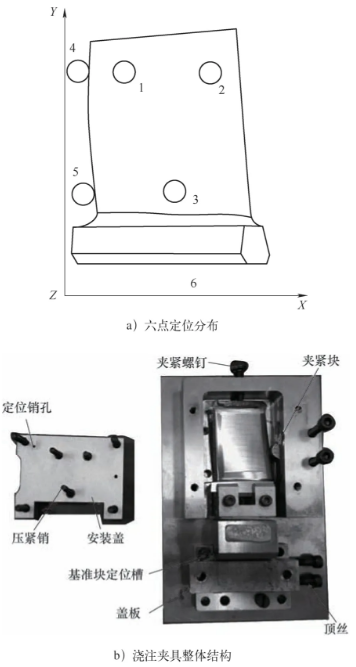
The process equipment in the traditional processing technology of aircraft engine blades is to use phase change materials such as low melting point alloys for filling auxiliary support. That is, after the workpiece blank is positioned and clamped at six points, the positioning reference of the workpiece is cast into a casting block through the low melting point alloy to provide auxiliary support for the workpiece, and the complex point positioning is converted into regular surface positioning, and then the precision processing of the part to be processed is carried out (see Figure 6). This process method has obvious defects: the positioning reference conversion leads to a decrease in positioning accuracy; the production preparation is complicated, and the casting and melting of the low melting point alloy also brings about residue and cleaning problems on the workpiece surface. At the same time, the casting and melting conditions are also relatively poor [30]. In order to solve the above process defects, a common method is to introduce a multi-point support structure combined with a phase change material [31]. The upper end of the support structure contacts the workpiece for positioning, and the lower end is immersed in the low melting point alloy chamber. Flexible auxiliary support is achieved based on the phase change characteristics of the low melting point alloy. Although the introduction of a support structure can avoid surface defects caused by low-melting-point alloys contacting the blades, due to the performance limitations of phase change materials, phase change flexible tooling cannot simultaneously meet the two major requirements of high stiffness and high response speed, and is difficult to apply to high-efficiency automated production.
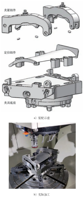
In order to solve the drawbacks of phase change flexible tooling, many scholars have incorporated the concept of adaptation into the research and development of flexible tooling. Adaptive flexible tooling can adaptively match complex blade shapes and possible shape errors through electromechanical systems. In order to ensure that the contact force is evenly distributed on the entire blade, the tooling usually uses multi-point auxiliary supports to form a support matrix. Wang Hui's team at Tsinghua University proposed a multi-point flexible auxiliary support process equipment suitable for near-net-shape blade processing [32, 33] (see Figure 7). The tooling uses multiple flexible material clamping elements to assist in supporting the blade surface of the near-net-shape blade, increasing the contact area of each contact area and ensuring that the clamping force is evenly distributed on each contact part and the entire blade, thereby improving the stiffness of the process system and effectively preventing local deformation of the blade. The tooling has multiple passive degrees of freedom, which can adaptively match the blade shape and its error while avoiding over-positioning. In addition to achieving adaptive support through flexible materials, the principle of electromagnetic induction is also applied to the research and development of adaptive flexible tooling. Yang Yiqing's team at Beijing University of Aeronautics and Astronautics invented an auxiliary support device based on the principle of electromagnetic induction [34]. The tooling uses a flexible auxiliary support excited by an electromagnetic signal, which can change the damping characteristics of the process system. During the clamping process, the auxiliary support adaptively matches the shape of the workpiece under the action of a permanent magnet. During the processing, the vibration generated by the workpiece will be transmitted to the auxiliary support, and the reverse electromagnetic force will be excited according to the principle of electromagnetic induction, thereby suppressing the vibration of thin-walled workpiece processing.
At present, in the process of process equipment design, finite element analysis, genetic algorithm and other methods are generally used to optimize the layout of multi-point auxiliary supports [35]. However, the optimization result can usually only ensure that the processing deformation at one point is minimized, and cannot guarantee that the same deformation suppression effect can be achieved in other processing parts. In the blade processing process, a series of tool passes are usually performed on the workpiece on the same machine tool, but the clamping requirements for processing different parts are different and may even be time-varying. For the static multi-point support method, if the rigidity of the process system is improved by increasing the number of auxiliary supports, on the one hand, the mass and volume of the tooling will increase, and on the other hand, the movement space of the tool will be compressed. If the position of the auxiliary support is reset when processing different parts, the processing process will inevitably be interrupted and the processing efficiency will be reduced. Therefore, follow-up process equipment [36-38] that automatically adjusts the support layout and support force online according to the processing process has been proposed. The follow-up process equipment (see Figure 8) can achieve dynamic support through the coordinated cooperation of the tool and tooling based on the tool trajectory and working condition changes of the time-varying cutting process before any processing procedure begins: first move the auxiliary support to a position that helps to suppress the current processing deformation, so that the processing area of the workpiece is actively supported, while other parts of the workpiece remain in position with as little contact as possible, thereby matching the time-varying clamping requirements during the processing process.
In order to further enhance the adaptive dynamic support capability of process equipment, match the more complex clamping requirements in the processing process, and improve the quality and efficiency of blade processing production, the follow-up auxiliary support is expanded into a group formed by multiple dynamic auxiliary supports. Each dynamic auxiliary support is required to coordinate actions and automatically and quickly reconstruct the contact between the support group and the workpiece according to the time-varying requirements of the manufacturing process. The reconstruction process does not interfere with the positioning of the entire workpiece and does not cause local displacement or vibration. The process equipment based on this concept is called a self-reconfigurable group fixture [39], which has the advantages of flexibility, reconfigurability and autonomy. The self-reconfigurable group fixture can allocate multiple auxiliary supports to different positions on the supported surface according to the requirements of the manufacturing process, and can adapt to complex-shaped workpieces with a large area, while ensuring sufficient rigidity and eliminating redundant supports. The working method of the fixture is that the controller sends instructions according to the programmed program, and the mobile base brings the support element to the target position according to the instructions. The support element adapts to the local geometric shape of the workpiece to achieve compliant support. The dynamic characteristics (stiffness and damping) of the contact area between a single support element and the local workpiece can be controlled by changing the parameters of the support element (for example, the hydraulic support element can usually change the input hydraulic pressure to change the contact characteristics). The dynamic characteristics of the process system are formed by the coupling of the dynamic characteristics of the contact area between multiple support elements and the workpiece, and are related to the parameters of each support element and the layout of the support element group. The design of the multi-point support reconstruction scheme of the self-reconfigurable group fixture needs to consider the following three issues: adapting to the geometric shape of the workpiece, rapid repositioning of the support elements, and coordinated cooperation of multiple support points [40]. Therefore, when using the self-reconfigurable group fixture, it is necessary to use the workpiece shape, load characteristics and inherent boundary conditions as input to solve the multi-point support layout and support parameters under different processing conditions, plan the multi-point support movement path, generate control code from the solution results, and import it into the controller. At present, domestic and foreign scholars have conducted some research and attempts on self-reconfigurable group fixtures. In foreign countries, the EU project SwarmItFIX has developed a new highly adaptable self-reconfigurable fixture system [41], which uses a set of mobile auxiliary supports to move freely on the workbench and reposition in real time to better support the processed parts. The prototype of the SwarmItFIX system has been implemented in this project (see Figure 9a) and tested at the site of an Italian aircraft manufacturer. In China, Wang Hui's team at Tsinghua University has developed a four-point clamping support workbench that can be controlled in coordination with a machine tool [42] (see Figure 9b). This workbench can support the cantilevered tenon and automatically avoid the tool during the fine machining of the tenon of a turbine blade. During the machining process, the four-point auxiliary support cooperates with the CNC machining center to reconstruct the four-point contact state according to the tool movement position, which not only avoids interference between the tool and the auxiliary support, but also ensures the support effect.
As the thrust-to-weight ratio design requirements of aircraft engines continue to increase, the number of parts is gradually reduced, and the stress level of parts is getting higher and higher. The performance of the two main traditional high-temperature structural materials has reached its limit. In recent years, new materials for aircraft engine blades have developed rapidly, and more and more high-performance materials are used to make thin-walled blades. Among them, γ-TiAl alloy[43] has excellent properties such as high specific strength, high temperature resistance and good oxidation resistance. At the same time, its density is 3.9g/cm3, which is only half of that of high-temperature alloys. In the future, it has great potential as a blade in the temperature range of 700-800℃. Although γ-TiAl alloy has excellent mechanical properties, its high hardness, low thermal conductivity, low fracture toughness and high brittleness lead to poor surface integrity and low precision of γ-TiAl alloy material during cutting, which seriously affects the service life of parts. Therefore, the processing research of γ-TiAl alloy has important theoretical significance and value, and is an important research direction of current blade processing technology.
Aeroengine blades have complex curved surfaces and require high shape accuracy. Currently, their precision machining mainly uses geometric adaptive machining methods based on path planning and model reconstruction. This method can effectively reduce the impact of errors caused by positioning, clamping, etc. on blade machining accuracy. Influence. However, due to the uneven thickness of the die forging blade blank, the cutting depth in different areas of the tool is different during the cutting process according to the planned path, which brings uncertain factors to the cutting process and affects the processing stability. In the future, during the CNC adaptive machining process, the actual machining state changes should be better tracked [44], thereby significantly improving the machining accuracy of complex curved surfaces and forming a time-varying control adaptive machining method that adjusts cutting parameters based on real-time feedback data.
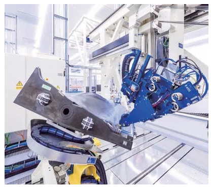
As the largest type of parts in the engine, the manufacturing efficiency of blades directly affects the overall manufacturing efficiency of the engine, and the manufacturing quality of blades directly affects the performance and life of the engine. Therefore, intelligent precision machining of blades has become the development direction of engine blade manufacturing in the world today. The research and development of machine tools and process equipment is the key to realizing intelligent blade processing. With the development of CNC technology, the intelligence level of machine tools has rapidly improved, and the processing and production capacity has been greatly enhanced. Therefore, the research and development and innovation of intelligent process equipment is an important development direction for efficient and precise machining of thin-walled blades. Highly intelligent CNC machine tools are combined with process equipment to form an intelligent blade processing system (see Figure 10), which realizes high-precision, high-efficiency and adaptive CNC machining of thin-walled blades.
 Hot News
2024-12-31
2024-12-04
2024-12-03
2024-12-05
2024-11-27
2024-11-26
Our professional sales team are waiting for your consultation.
 EN
EN
 AR
AR
 BG
BG
 HR
HR
 CS
CS
 DA
DA
 NL
NL
 FI
FI
 FR
FR
 DE
DE
 EL
EL
 HI
HI
 IT
IT
 JA
JA
 KO
KO
 NO
NO
 PL
PL
 PT
PT
 RO
RO
 RU
RU
 ES
ES
 SV
SV
 TL
TL
 IW
IW
 LV
LV
 LT
LT
 SR
SR
 SK
SK
 SL
SL
 UK
UK
 VI
VI
 ET
ET
 HU
HU
 TH
TH
 TR
TR
 AF
AF
 MS
MS
 GA
GA
 IS
IS