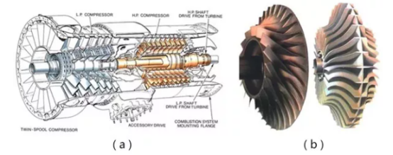
Although there are differences in the functions and structures of compressor and turbine rotors, in terms of strength, the working conditions of the wheels of the two are roughly the same. However, the turbine disk is at a higher temperature, which means that the working environment of the turbine disk is more harsh.
The impeller must withstand the centrifugal force of the blades and impeller itself caused by the rotation of the rotor. The following speed conditions should be considered in strength calculation:
Steady-state operating speed at the strength calculation point specified within the flight envelope;
Maximum allowable steady-state operating speed specified in the model specification;
115% and 122% of the maximum allowable steady-state operating speed.
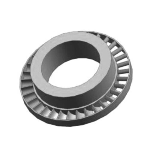
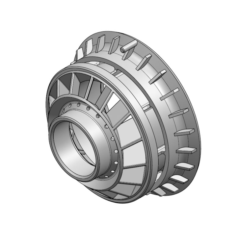
The blades, locks, baffles, bolts, nuts and screws installed on the disc are all located at the edge of the wheel disc. Usually, the outer edge of the wheel disc is at the bottom of the groove. Assuming that these loads are evenly distributed on the surface of the outer edge of the wheel disc, the uniform load is:
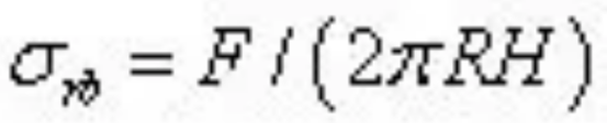
Where F is the sum of all external loads, R is the radius of the outer circle of the wheel, and H is the axial width of the outer edge of the wheel.
When the bottom of the mortise and tenon groove is parallel to the rotation axis of the wheel disc, the outer edge radius is taken as the radius of the position where the bottom of the groove is located; when the bottom of the mortise and tenon groove has an inclination angle in the radial direction with the rotation axis of the wheel disc, the outer edge radius is approximately taken as the average value of the front and rear edge groove bottom radii.
The wheel disc has to bear the thermal load caused by uneven heating. For the compressor disc, the thermal load can generally be ignored. However, with the increase of the engine's total pressure ratio and flight speed, the compressor outlet airflow has reached a very high temperature. Therefore, the thermal load of the discs before and after the compressor is sometimes not negligible. For the turbine disc, thermal stress is the most important influencing factor after centrifugal force. The following types of temperature fields should be considered during calculation:
Steady-state temperature field for each strength calculation specified in the flight envelope;
Steady-state temperature field in a typical flight cycle;
Transition temperature field in a typical flight cycle.
When estimating, if the original data cannot be fully provided and there is no measured temperature for reference, the airflow parameters under the design state and the highest heat load state can be used for estimation. The empirical formula for estimating the temperature field on the disk is:
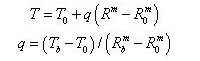
In the formula, T is the temperature at the required radius, T0 is the temperature at the center hole of the disk, Tb is the temperature at the rim of the disk, R is an arbitrary radius on the disk, and the subscripts 0 and b correspond to the center hole and rim, respectively.
m=2 corresponds to titanium alloy and ferritic steel without forced cooling;
m=4 corresponds to nickel-based alloy with forced cooling.
Steady-state temperature field:
When there is no cooling airflow, it can be considered that there is no temperature difference;
When there is cooling airflow, Tb can be approximately taken as the outlet temperature of the airflow at each level of the channel + 15℃, and T0 can be approximately taken as the outlet temperature of the airflow at the extraction cooling airflow level + 15℃.
Transient temperature field:
Tb can be approximately taken as the outlet temperature of each level of channel airflow;
T0 can be approximately taken as 50% of the wheel rim temperature when there is no cooling airflow; when there is cooling airflow, it can be approximately taken as the outlet temperature of the cooling airflow extraction stage.
Steady-state temperature field:
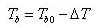
Tb0 is the cross-sectional temperature of the blade root; △T is the temperature drop of the tenon, which can be taken approximately as follows: △T=50-100℃ when the tenon is not cooled; △T=250-300℃ when the tenon is cooled.
Transient temperature field:
The disk with cooling blades can be approximated as follows: transient temperature gradient = 1.75 × steady-state temperature gradient;
The disk without cooling blades can be approximated as follows: transient temperature gradient = 1.3 × steady-state temperature gradient.
For compressor blades, the gas force component acting on unit blade height is:
Axial:
Where Zm and Q are the average radius and number of blades; ρ1m and ρ2m are the density of airflow at the inlet and outlet sections; C1am and C2am are the axial velocity of airflow at the average radius of the inlet and outlet sections; p1m and p2m are the static pressure of airflow at the average radius of the inlet and outlet sections.
Circumferential direction: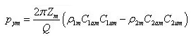
The direction of the gas force on the gas is different from the two formulas above by a negative sign. There is generally a certain pressure in the cavity between the two-stage impeller (especially the compressor impeller). If the pressure in the adjacent spaces is different, a pressure difference will be caused on the impeller between the two cavities, △p=p1-p2. Generally, △p has little effect on the static strength of the impeller, especially when there is a hole in the impeller spoke, △p can be ignored.
For large diameter fan disks with fan blades, the effect of gyroscopic moments on the bending stress and deformation of the disk should be considered.
The vibration stress generated in the disk when the blades and disks vibrate should be superimposed with the static stress. The general dynamic loads are:
The periodic non-uniform gas force on the blades. Due to the presence of the bracket and the separate combustion chamber in the flow channel, the airflow is uneven along the circumference, which produces a periodic unbalanced gas exciting force on the blades. The frequency of this exciting force is: Hf = ωm. Among them, ω is the speed of the engine rotor, and m is the number of brackets or combustion chambers.
The periodic non-uniform gas pressure on the disk surface.
The exciting force transmitted to the disk through the connected shaft, connecting ring or other parts. This is due to the imbalance of the shaft system, which causes the vibration of the whole machine or the rotor system, thereby driving the connected disk to vibrate together.
There are complex interference forces between the blades of the multi-rotor turbine, which will affect the vibration of the disk and plate system.
Disk coupling vibration. The disk edge coupling vibration is related to the inherent vibration characteristics of the disk system. When the exciting force on the disk system is close to a certain order of dynamic frequency of the system, the system will resonate and generate vibration stress.
The interference fit between the disk and the shaft will generate assembly stress on the disk. The magnitude of the assembly stress depends on the interference fit, the size and material of the disk and the shaft, and is related to other loads on the disk. For example, the existence of centrifugal load and temperature stress will enlarge the center hole of the disk, reduce the interference, and thus reduce the assembly stress.
Among the above-mentioned loads, mass centrifugal force and thermal load are the main components. When calculating the strength, the following combinations of rotation speed and temperature should be considered:
The speed of each strength calculation point specified in the flight envelope and the temperature field at the corresponding point;
The steady-state temperature field at the maximum heat load point or the maximum temperature difference in flight and the maximum allowable steady-state operating speed, or the corresponding steady-state temperature field when the maximum allowable steady-state operating speed is reached in flight.
For most engines, takeoff is often the worst stress state, so the combination of the transient temperature field during takeoff (when the maximum temperature difference is reached) and the maximum operating speed during takeoff should be considered.
 Hot News
2024-12-31
2024-12-04
2024-12-03
2024-12-05
2024-11-27
2024-11-26
Our professional sales team are waiting for your consultation.
 EN
EN
 AR
AR
 BG
BG
 HR
HR
 CS
CS
 DA
DA
 NL
NL
 FI
FI
 FR
FR
 DE
DE
 EL
EL
 HI
HI
 IT
IT
 JA
JA
 KO
KO
 NO
NO
 PL
PL
 PT
PT
 RO
RO
 RU
RU
 ES
ES
 SV
SV
 TL
TL
 IW
IW
 LV
LV
 LT
LT
 SR
SR
 SK
SK
 SL
SL
 UK
UK
 VI
VI
 ET
ET
 HU
HU
 TH
TH
 TR
TR
 AF
AF
 MS
MS
 GA
GA
 IS
IS