The combustion chamber is one of the core components of an aircraft engine, and the aerodynamic performance of the combustion chamber plays a vital role in the performance of the entire engine. In order to meet the increasingly stringent technical requirements of the engine for the combustion chamber, the combustion organization mode and flow characteristics inside the combustion chamber have become very complex. The deceleration and pressurization process of the diffuser may face flow separation under a strong adverse pressure gradient; the airflow passes through a multi-stage swirl device to form a large-scale vortex structure, which on the one hand promotes the atomization and evaporation of the liquid fuel and forms a strongly pulsating, unsteady mixture with the fuel, and on the other hand generates a stationary flame in the aerodynamic recirculation zone; the multiple jets of the main combustion/mixing hole interact with the lateral flow in the flame tube to form a counter-rotating vortex pair, which has an important influence on turbulent mixing. On the basis of flow, multi-scale physical and chemical processes such as atomization and evaporation, mixing, chemical reaction, and interaction between turbulence and flame are strongly coupled, which jointly determine the aerodynamic characteristics of the combustion chamber. The high-precision modeling and calculation of these physical and chemical processes have always been a hot topic of research at home and abroad.
The atomization, evaporation, mixing and combustion processes in the combustion chamber develop and evolve in a turbulent flow environment, so flow is the basis for the simulation of the aerodynamic performance of the combustion chamber. The basic characteristic of turbulence is that the flow parameters show random pulsation due to the nonlinear convection process. Turbulence contains many vortex structures. The spans of different vortices in length and time scales are huge, and as the Reynolds number increases, the spans between scales increase sharply. According to the proportion of turbulent vortex structures that are directly solved, turbulence simulation methods are divided into direct numerical simulation (DNS), Reynolds-Averaged Navier-Stokes (RANS), large eddy simulation (LES) and mixed turbulence simulation methods. The RANS method, which is widely used in engineering, solves the turbulent mean field and uses a model to simulate all turbulent pulsation information. The calculation amount is small, but the accuracy is poor. For strong swirl and unsteady flow processes in the combustion chamber, RANS cannot meet the requirements of refined design. Pitsch pointed out that the computational complexity of LES is between RANS and DNS, and is currently used for turbulent combustion calculations in unrestricted spaces with medium and low Reynolds numbers. Due to the small scale of turbulence in the near-wall area of the combustion chamber and the high Reynolds number of the flow, the amount of grids required for LES calculation of a single head of the combustion chamber alone is in the hundreds of millions to billions. Such high computational resource consumption limits the widespread use of LES in combustion chamber simulations.
The establishment of high-precision calculation models and methods based on the Very Large Eddy Simulation (VLES) and Hybrid RANS-LES Method frameworks is an important trend in numerical simulation. The VLES method developed by Han et al. solves the problem of low computational efficiency caused by filtering grid scale and solving turbulence scale matching restrictions in traditional LES, and realizes coupling modeling between turbulence multi-scale characteristics, transient evolution characteristics, and grid resolution. , VLES adaptively adjusts the ratio between turbulence solution and model modeling based on the real-time characteristics of the vortex structure evolution, significantly reducing computational costs while ensuring calculation accuracy.
Nevertheless, compared with traditional LES, the theory and characteristics of VLES have not been widely studied and used. This paper systematically introduces the modeling theory of VLES and its application effects in various physical scenarios related to combustion chambers, promoting the large-scale application of VLES in the field of aircraft engine combustion chamber simulation.
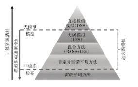
The influence of turbulence simulation methods on computing resource consumption and models is shown in Figure 1. RANS, LES and VLES methods all achieve flow simulation through turbulence modeling. It should be noted that the earliest clear definition of VLES was given by Pope, which refers to "the computational grid scale is too coarse so that the turbulent kinetic energy directly solved is less than 80% of the total turbulent kinetic energy". At the same time, the meaning of LES given by Pope [6] is "the computational grid is very fine so that the turbulent kinetic energy directly solved is greater than 80% of the total turbulent kinetic energy". Nevertheless, it should be noted that the VLES introduced in this article is a new computational method that has been remodeled and developed on the basis of the previous method. Although the names are the same, the new VLES method is essentially different from the VLES method defined by Pope. As can be seen from the figure, the traditional turbulence modes are RANS, URANS, hybrid RANS/LES, LES, and DNS in order of calculation accuracy. Under the new model framework, the turbulence modes are divided into RANS, VLES, and DNS in order of calculation accuracy. That is, the VLES method realizes the unification of multiple traditional turbulence modes, and different models adaptively transition and convert smoothly according to local characteristics in actual calculations.
The combustion chamber of an aircraft engine usually adopts flow field organization forms such as multi-stage swirl and strong swirl. Swirl flow is the most basic flow form in the combustion chamber. Since swirl is dominant in both the flow direction and the tangential direction, the turbulent pulsation of swirl has stronger anisotropy than traditional pipe flow, channel flow and jet flow. Therefore, the numerical simulation of swirl poses a great challenge to the turbulence simulation method. Xia et al. used the VLES method to calculate the classic strong swirl flow example in the tube; Dellenback et al. [14] conducted flow field experiments on this example and have detailed experimental data. The flow Reynolds number of the calculated example is 1.0×10⁵ (based on the diameter of the circular tube) and the swirl number is 1.23. Two sets of structured grids are used in the calculation. The total number of sparse grids (M1) is about 900,000 and the total number of encrypted grids (M2) is about 5.1 million. The statistical moment results obtained by calculation are further compared with the experimental results to verify the calculation accuracy of the VLES method.
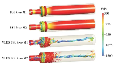
The comparison of the calculation results of different methods and the experimental results of the radial distribution of the circumferential average velocity and pulsating velocity at different downstream positions under strong swirling flow is shown in Figure 4. In the figure, the horizontal and vertical coordinates are dimensionless distance and dimensionless velocity, respectively, where D1 is the diameter of the inlet circular pipe and Uin is the inlet average velocity. As can be seen from the figure, the flow field shows a typical Rankin-like compound vortex gradually transitioning to a single rigid body vortex. Comparing the calculation and experimental results, it can be found that the VLES method has a high calculation accuracy for the prediction of the circumferential velocity of strong swirling flow, which is in good agreement with the distribution of experimental measurements. The traditional RANS method has a very large deviation in the calculation of swirl flow and cannot correctly predict the spatial evolution of the swirl flow field and turbulent pulsation. In comparison, the VLES method has a very high accuracy in the prediction of the average velocity field, pulsating velocity field and spatial evolution under complex strong swirling flow, and can still guarantee a high calculation accuracy even at a relatively sparse grid resolution. For the prediction of the circumferential average velocity, the calculation results of the VLES method are basically consistent at two sets of sparse and dense grid resolutions.
In order to study the feasibility of the VLES method in predicting turbulent combustion problems [15-16], a turbulent combustion model based on the VLES method coupled with the flamelet generated manifolds (FGM) was developed. The basic idea is to assume that the turbulent flame has a one-dimensional laminar flame structure locally, and the turbulent flame surface is the ensemble average of a series of laminar flame surfaces. Therefore, the high-dimensional component space can be mapped to a low-dimensional flow pattern composed of several characteristic variables (mixture fraction, reaction progress variable, etc.). Under the condition of considering the detailed reaction mechanism, the number of transport equations to be solved is greatly reduced, thereby significantly reducing the computational cost.
The specific implementation process is to construct the FGM laminar data table based on the mixture fraction and reaction progress variables, consider the interaction between turbulent combustion by assuming the probability density function method to integrate the laminar data table, and thus obtain the turbulent data table. In the numerical calculation, the transport equations of the mixture fraction, reaction progress variables and the corresponding variance are solved, and the combustion field information is obtained by querying the turbulent data table.
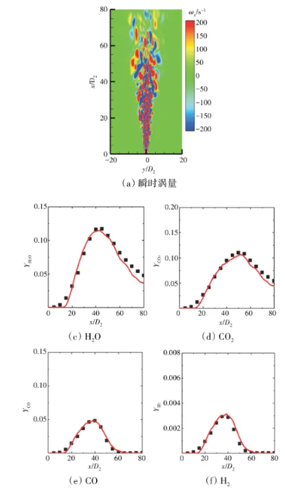
The turbulent combustion model based on VLES and FGM was used to carry out numerical calculations on the methane/air turbulent jet flame (Flame D) measured by the Sandia laboratory in the United States, and quantitative comparisons were made with the experimental measurement data. The fuel material of the Sandia Flame D example (Reynolds number is 22400) is a complete mixture of methane and air with a volume ratio of 1:3, the fuel inlet velocity is about 49.9 m/s, and the wake velocity is about 11.4 m/s. The duty flame is a mixture of burned methane and air, and the wake material is pure air. The calculation uses a structured grid, and the total number of grids is about 1.9 million.
The distribution of the average mass fraction of different components along the axis is shown in Figure 5. The horizontal and vertical coordinates in the figure are dimensionless distance (D2 is the diameter of the inlet jet tube) and dimensionless mass fraction, respectively. It can be seen from the figure that the prediction of the main components of the combustion process by the VLES method is generally in good agreement with the experimental results. The scattered distribution of the temperature at different downstream positions in the mixture fraction space is shown in Figure 6. It can be seen from the figure that the scattered distribution trend predicted by the VLES method is basically consistent with the experimental results, and only the calculated temperature extreme value is slightly higher than the experimental value. The distribution of the instantaneous vorticity, temperature and resolution control function calculated by VLES is shown in Figure 7, where the solid line is taken as Zst=0.351. It can be seen from the figure that the core jet area exhibits strong turbulent pulsation, and as the flow field develops downstream, the scale of the vortex structure gradually increases. As can be seen from Figure 7 (b) and (c), in most chemical reaction areas, the resolution control function is between 0 and 1, indicating that the local grid resolution can capture large-scale turbulence and only simulate small-scale turbulence through the model. At this time, VLES behaves as an approximate large eddy simulation solution mode. In the jet shear layer and the outer edge of the downstream flame, the resolution control function is close to 1, indicating that the truncated filter scale of the computational grid is larger than the local turbulence scale. At this time, VLES behaves as an unsteady Reynolds average solution mode. In summary, it can be seen that the VLES method can realize the transformation of multiple turbulence solution modes according to the real-time characteristics of the vortex structure evolution, and can accurately predict the unsteady combustion process in turbulent flames.
Most of the fuel used in the combustion chamber of an aircraft engine is liquid fuel. Liquid fuel enters the combustion chamber and undergoes primary atomization and secondary atomization processes. There are many difficulties in simulating the complete atomization process of liquid fuel, including the capture of the gas-liquid two-phase topological interface configuration, liquid column deformation and rupture, the breakup evolution of liquid bands and liquid filaments into droplets, and the interaction between turbulent flow and droplets. Huang Ziwei [19] developed a complete atomization process simulation model based on the VLES method coupled with the VOFDPM hybrid atomization calculation method, realizing the full-process numerical simulation of fuel atomization from continuous liquid to discrete droplets.
A newly developed atomization process simulation model was used to carry out high-precision numerical calculations of the classic lateral flow liquid column atomization process, and a detailed comparison was made with the experimental results in the open literature [20] and the large eddy simulation calculation results [21]. In the calculation example, the gas phase is air with velocities of 77.89 and 110.0 m/s, respectively, and the liquid phase is liquid water with a velocity of 8.6 m/s. The corresponding Weber numbers are 100 and 200, respectively. In order to better simulate the secondary breakup process, the breakup model adopts the Kelvin-Helmholtz and Rayleigh-Taylor (KHRT) model.
The complete atomization process predicted by VLES under the Weber number 100 condition is shown in Figure 8. As can be seen from the figure, a thin sheet of liquid column is formed in the initial area, and then the liquid column breaks into liquid bands and liquid filaments, and breaks into droplets under the action of aerodynamic force, and the droplets are further broken into smaller droplets through secondary breakup. The stream velocity and spanwise vorticity distribution calculated by VLES under the Weber number 100 condition are shown in Figure 9. As can be seen from the figure, there is a typical low-speed recirculation zone on the leeward side of the liquid column. It can be found from the instantaneous vorticity distribution that the leeward side of the liquid column exhibits a strong vortex structure, and the strong turbulent motion in the low-speed recirculation zone contributes to the rupture of the liquid column sheet and the formation of droplets.
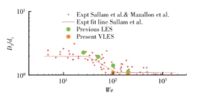
The ratio of the initial jet diameter to the minimum flow dimension of the liquid jet when the liquid column begins to break up under different Weber numbers is shown in Figure 10. In the figure, di is the minimum flow dimension of the liquid jet when the liquid column begins to break up, and D3 is the initial liquid jet diameter. It can be seen from the figure that the VLES calculation results are in good agreement with the experimental results, which are better than the large eddy simulation calculation results in the literature [21].
In order to meet the requirements of low emissions, civil aircraft combustion chambers are usually designed with premixed or partially premixed lean combustion. However, lean premixed combustion has poor stability and is prone to excite thermoacoustic coupled oscillation combustion modes, leading to combustion instability. Combustion instability is highly destructive and may be accompanied by problems such as flashback and solid deformation, which is a prominent problem faced by combustion chamber design.
The numerical calculation of combustion instability can be divided into two categories: decoupling method and direct coupling method. The decoupled combustion instability prediction method decouples the unsteady combustion and acoustic solutions. Unsteady combustion requires a large number of numerical calculation samples to build a reliable flame description function. If the large eddy simulation calculation method is used, its computing resources consumption is too large. The direct coupling calculation method is based on the compressible solution method, and directly obtains the result of combustion instability through high-precision unsteady calculation, that is, the coupling calculation process of unsteady combustion and acoustics under given working conditions is completed at one time within the same calculation framework.
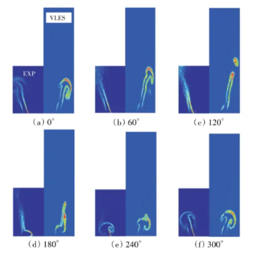
In the study of numerical simulation of combustion instability decoupling, Huang et al. [27] developed a combustion instability calculation model based on the VLES method coupled with the thickening flame calculation method, and achieved accurate prediction of the unsteady combustion process under acoustic excitation. The calculation example is a blunt body stationary ethylene/air fully premixed flame developed by Cambridge University, with an equivalence ratio of 0.55 and a Reynolds number of about 17000. The comparison between the VLES calculation results and the experimental results of the unsteady flame dynamic characteristics under acoustic excitation is shown in Figure 12. It can be seen from the figure that during the inlet excitation process, the flame rolls over at the inner and outer shear layers and evolves into a counter-rotating vortex pair. In this process, the evolution of the mushroom-shaped flame profile continues to develop with the change of the phase angle. The VLES calculation results well reproduce the flame evolution characteristics observed in the experiment. The comparison of the amplitude and phase difference of the heat release rate response under 160 Hz acoustic excitation obtained by different calculation methods and experimental measurements is shown in Figure 13. In the figure, Q' and Q͂ are the pulsating heat release and average heat release of combustion, respectively, A is the amplitude of sinusoidal acoustic excitation, and the ordinate of Figure 13 (b) is the phase difference between the transient heat release signal of combustion under acoustic excitation and the inlet velocity excitation signal. As can be seen from the figure, the prediction accuracy of the VLES method is comparable to the accuracy of large eddy simulation [28], and both are in good agreement with the experimental values. Although the unsteady RANS method predicts the trend of nonlinear response, the calculated quantitative results deviate greatly from the experimental values. For the phase difference results (Figure 13 (b)), the trend of the phase difference predicted by the VLES method with the disturbance amplitude is basically consistent with the experimental results, while the large eddy simulation results do not predict the above trend well.
 Hot News
2025-12-31
2024-12-31
2024-12-04
2024-12-03
2024-12-05
2024-11-27
Our professional sales team are waiting for your consultation.
 EN
EN
 AR
AR
 BG
BG
 HR
HR
 CS
CS
 DA
DA
 NL
NL
 FI
FI
 FR
FR
 DE
DE
 EL
EL
 HI
HI
 IT
IT
 JA
JA
 KO
KO
 NO
NO
 PL
PL
 PT
PT
 RO
RO
 RU
RU
 ES
ES
 SV
SV
 TL
TL
 IW
IW
 LV
LV
 LT
LT
 SR
SR
 SK
SK
 SL
SL
 UK
UK
 VI
VI
 ET
ET
 HU
HU
 TH
TH
 TR
TR
 AF
AF
 MS
MS
 GA
GA
 IS
IS